The most common flow velocity measurement device is probably the Pitot-static probe (used in experiment 3). This is a rugged and inexpensive device that in many situations can be used to give accurate and reliable velocity measurements. However, Pitot-static probes cannot measure velocity fluctuations associated with turbulence or unsteadiness. Furthermore the time average velocities they can measure are inaccurate in regions where the flow is highly turbulent, reversing or of unknown direction (as in the center of the wake of a circular cylinder). Unfortunately such regions are often of the greatest engineering interest.
There is therefore a need for more sophisticated measurement techniques. The two most commonly used in industry, government and universities are laser Doppler anemometry and hot-wire anemometry. The purpose of experiment 4 is to introduce you to laser Doppler anemometry (LDA). You will experience hot-wire anemometry in the senior lab course. In this chapter you will read about the principles of LDA. In the experiment you will gain hands-on practical experience of this leading-edge technology.
A laser Doppler anemometer measures the velocity at a point in a flow using light beams. It senses true velocity component, and measures that component in a sequence of near instantaneous samples. These characteristics confer several advantages - an LDA does not disturb the flow being measured (like a Pitot does), it can be used in flows of unknown direction and it can give accurate measurements in unsteady and turbulent flows where the velocity is fluctuating with time. Among the disadvantages of LDAs are expense (typically $40,000 for a simple system), the need for a transparent flow through which the light beams can pass, and the fact that they do not give continuous velocity signals.
Basic principles
The easiest way to understand how a laser Doppler anemometer works
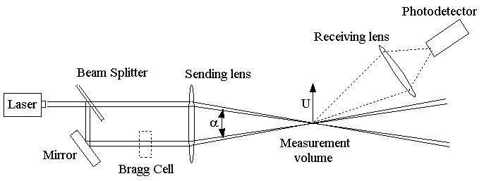
is to consider a specific example. Figure 1
shows a "One-component dual-beam system". One component because
it measures one specific velocity component (U in the diagram). Dual
beam because it uses two laser beams of equal intensity. The beams
are generated from a single laser using a half silvered mirror (the 'beam
splitter'). They are then focused using a lens (called the sending
lens). The lens also changes the direction of the beams causing them to
cross at the point where they are focused. The region where the beams
intersect is where the velocity measurement is made. It is called the measurement
volume.
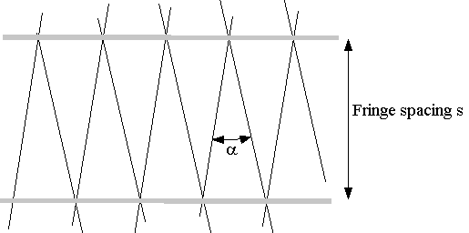
The interference of the light beams in the measurement volume creates a set of equally spaced fringes (light and dark bands) that are parallel to the bisector of the beams (figure 2). A measurement is made when a tiny particle being carried by the flow passes through these fringes. As it does so the amount of light received by the particle fluctuates with the fringes. The amount of light scattered (i.e. reflected) by the particle therefore also fluctuates. The frequency of this fluctuation is proportional to the velocity of the particle normal to the fringes.
To detect this frequency, the light scattered by the particle is collected by a second lens (the receiving lens) and focussed onto a photodetector (figure 1 ) which converts the fluctuations in light intensity into fluctuations in a voltage signal. An electronic device known as a signal processor is then used to determine the frequency of the signal and therefore the velocity of the flow.
Below we describe in more detail each of the elements of an LDA system. If, after reading this material, you wish to find out more about LDA, then a detailed treatment may be found in Durst et al. (1981).
Generation of the fringes
Figure 2 shows schematically the arrangement
of the light waves within the two beams. The waves are represented by lines
showing where the peaks are. Since laser light is monochromatic (i.e. of
one frequency and wavelength) and coherent (all adjacent and successive
waves are in phase) all the peaks line up. In the measurement volume the
two sets of light waves cross. Where the interfering light waves are in
phase (peak aligned with peak) they add up creating a bright fringe. Where
the light waves are out of phase (peak aligned with trough) they cancel
creating a dark fringe. As can be seen in Figure
2 , the bright and dark fringes form in lines parallel to the bisector
of the beams.
To calculate the spacing between the fringes we need to know the wavelength
of the laser light![]() and
the angle between the beams a. Consider the enlarged region shown in Figure 3
. We see that adjacent bright fringes and light waves form an isosceles
triangle of angle a
and base l/cos(a/2). Using trigonometry, verify for yourself that the height of the triangle,
the fringe spacing s, is ½l/sin(a/2).
and
the angle between the beams a. Consider the enlarged region shown in Figure 3
. We see that adjacent bright fringes and light waves form an isosceles
triangle of angle a
and base l/cos(a/2). Using trigonometry, verify for yourself that the height of the triangle,
the fringe spacing s, is ½l/sin(a/2).
With the fringe spacing we can now determine the relationship between the velocity of the particle and the frequency it generates. If the fringes are a distance s apart and the velocity component of the particle normal to the fringes and in the plane of the beams is U, then the particle will cross a total of U/s fringes per second. Thus the particle will generate a signal of frequency f = U/s = 2Usin(a/2)/l. This important expression, known as the LDA equation, enables us to relate the frequency f of signals from an LDA to the velocity of the flow U.
We can use the LDA equation now to get an order of magnitude estimate of the frequency produced by a particle traversing a typical measurement volume. The wavelength of light from a Helium Neon laser (one of many types used in this application) is 632.8 nanometers. The angle between the laser beams in a dual beam system will typically be about 5 degrees. If we use such an anemometer to measure a flow of velocity 10 m/s then the above equation tells us that signals of 1.4MHz will be produced when a particle traverses the measurement volume. The high frequencies of LDA signals place stiff requirements on the dynamic response and speed of processing electronics.
Particles
As mentioned above tiny particles must be present in the flow for a
measurement to be made. These are referred to as seed particles,
or just seeding . It is important that these particles be small
enough to accurately follow all the movements of the flow. That way, when
we measure the velocity of the particles, we are also measuring the velocity
of the flow. Except in extreme circumstances, such as flow through shock
waves, 1-micron (10-6-meter) diameter
particles are usually small enough. Such particles are present naturally
in tap water but must be artificially introduced into air flows. Materials
used for particles include latex (as in latex paint) or oil, water or dioctal
phthalate droplets.
Note that, even in well seeded flows, the particles form only a minuscule fraction of the volume of the fluid. They therefore have no significant effect upon the flow.
Scattered-light detection
The light scattered by the particles is focused using a lens onto
a photodetector - most often a photomultiplier tube (or PM tube). PM tubes
contain a number of components sealed in a vacuum tube. At the front of
the PM tube is photocathode - a piece of material that emits electrons
when exposed to light. These electrons are then accelerated in an electric
field towards sequence of dynodes. When these high energy electrons collide
with the first dynode it emits more electrons which are then accelerated
into another dynode, and so on. The resulting avalanche of electrons greatly
amplifies the original signal. PM tubes are well suited to LDA applications.
They have very good dynamic response (to 100's of MHz and higher) and are
good for detecting weak signals. They require high-voltage supplies to
produce the electric field (typically 1000V).
Maximizing the signal
Even with a PM tube, detection of the light scattered by a 1 micron
diameter particle may not be an easy task. It is therefore important to
have a feel for those factors that influence the magnitude of this signal.
1. Focusing of the laser beams. Because they are coherent and
monochromatic, the laser beams focus to a very small diameter. The light
intensity in the measurement volume can therefore be huge. For example,
if the beams have a combined power of (10 milliWatts, small by most standards)
but focus to form a measurement volume 0.3mm in diameter, then the light
intensity in the measurement volume is approximately 0.01/(0.0003)2
»100000W/m2.
2. Optimizing the seeding. To get the strongest light signal
it is best to arrange the seeding (if possible) so that there is never
more than one particle in the measurement volume at any given time. If
multiple particles are present then the signals they produce will, most
likely, cancel out.
3. The direction in which the light is collected. The amount
of light scattered by the particles is a strong function of direction relative
to the incident beams. (Physically this is because the size of the particles
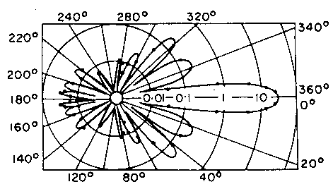
is comparable to the wavelength of the light.) Figure
4 shows the relative intensity of light scattered in different directions
relative to the incident beams for a typical beam wavelength and particle
size. Most of the light is scattered in the direction of the beams (to
the right in the figure). Thus many LDA systems are arranged with the receiving
lens and photodetector on the opposite side of the flow to the laser -
these are called forward scatter systems. Figure
1 is a forward scatter system. Unfortunately it is often necessary
to have all the equipment on the same side of the flow, or there is simply
no clear optical path through the far side of the flow. In this case it
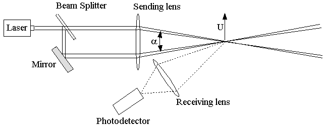
is the light that scatters back towards the laser is collected - as you
can see this is much weaker. We call such LDAs (e.g.
Figure 5 ) back scatter systems.
4. The receiving lens. The proportion of the scattered light
that is focused on to the photodetector increases with the area of the
lens and decreases as the inverse square of the distance from the measurement
volume to the lens. Using a larger lens, and putting it closer to the measurement
point can therefore greatly increase the magnitude of the detected signal.
5. Use of a pinhole. A pinhole is a mask placed over the front
of the photodetector that admits light only through a small hole located
at the point where scattered light from the measurement volume is focused.
The pinhole prevents light scattered from other parts of the beams or apparatus
from entering the detector and producing noise. Such noise can easily drown
the signal. The pinhole can also be used to restrict the measurement volume
size by making it small enough to admit light only from a portion of the
measurement volume.
The problem of directional ambiguity - frequency shifting
As we have described it so far, an LDA system effectively measures
the frequency at which a particle crosses a series of equally spaced fringes
( Figure 2). This technique has two serious
limitations - a stationary particle produces no signal and, more seriously,
two particles moving with the same speed but in opposite directions will
give rise to indistinguishable signals.
Both problems may be solved by slightly shifting the frequency of one of the laser beams. This causes the fringes in the measurement to volume to move at a constant speed in the U or -U directions depending on the direction of the frequency shift. Stationary particles exposed to these moving fringes now produce signals of constant frequency (this frequency turns out to be the same as the frequency shift). Particles moving with the fringes produce signals of lower frequency than this and particles moving against the fringes produce signals of higher frequency, the frequency difference still being determined by the LDA equation. The directional ambiguity is thus removed.
The most common device used to produce the frequency shift is called a Bragg cell. The Bragg cell contains a transparent medium (either liquid or solid) through which the laser beam passes. The medium is excited by passing ultrasonic sound waves through it. These sound waves (which are also density waves and therefore waves of refractive index) diffract the laser beam. Since they are moving they also shift its frequency, by an amount equal to the frequency of the sound wave.
Signals and signal processing
The electronic signal given out by the photodetector contains periods
of silence (while there are no particles in the measurement volume) randomly
interspersed with bursts of signal (when a particle passes through the
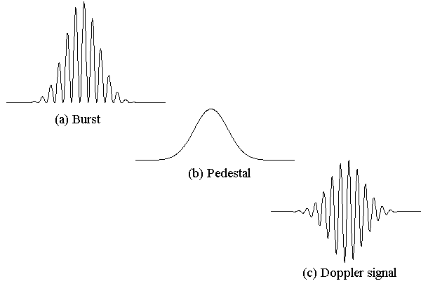
measurement volume). Figure 6 shows a idealized
signal burst. The overall shape of the burst is a consequence of the fact
that the laser beams producing the measurement volume will inevitably be
stronger at their center than at their edges. As the particle passes through
the edge of the measurement volume where the fringes are weakly illuminated
the signal fluctuations are also weak. As the particle passes through the
measurement volume center the signal fluctuations become larger and then
decay again. Note that the fluctuations are not centered about zero because
you cannot have a negative light intensity. As a consequence the signal
can be split into two parts - a low frequency part called the 'pedestal'
and a high frequency part that actually contains the Doppler signal.
Modern signal processors use digital technology to analyze each burst and extract the frequency and thus velocity at that instant. The hardware has to be quite sophisticated because the frequencies are so high. Typically such processors have 'burst-detection' circuits to tell them when there is a signal. They then digitize that signal and determine its frequency. To determine the frequency processors either autocorrelate the signal or take its Fourier spectrum . Thus we talk about 'autocorrelation processors' or 'burst spectrum analyzers'.
Sources of error
Laser Doppler anemometers are among the most accurate flow measurement
devices. However, they are not immune to errors and, as with any other
measurement technique, it is important to know the sources of error when
making an LDA measurement.
Particle averaging bias
One problem with laser Doppler anemometers is that they only sense
the velocity when there is a particle in the measurement volume. Thus when
using an LDA one collects a sequence of velocity samples each generated
when a particle passed. Unfortunately such a set of samples is biased -
when the flow velocity is high, more particles will pass through the volume
in a given time than when it is low. When we simply average the velocity
samples we will get an estimate of the mean flow velocity that is too large.
The estimated velocity variance will also be in error. This is called particle
averaging bias . It is largest when measuring air flows (where there
isn't usually much seeding) and/or reversing flows in which the velocity
can instantaneously be very small. There are several fixes that one can
use to try to minimize this problem that are currently a topic of debate
in the research community. One solution is collect only the first sample
in each of a series of fixed time periods. We will meet the issue of particle
average bias again in the LDA system software used in this experiment.
Velocity gradient broadening
Velocity gradient broadening tends to increase the measured variance
of the velocity signal by an amount given by (D¶U/¶y)2.
Here ¶U/¶y
is the mean velocity gradient at the point where the measurement is being
made and D is the
standard deviation of the distribution with Y of particles passing
through the measurement volume (typically D
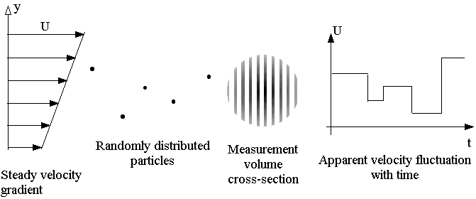
is about 1/4 of the measurement volume diameter). The source of this error
is illustrated in Figure 7 which shows a cross
section through the measurement volume. If the measurement is being made
in a flow with a velocity gradient (such as a boundary layer) then successive
particles passing through the measurement volume may have different velocities
by virtue of their different positions in the gradient. So, even if the
flow is completely steady, the LDA will measure a velocity fluctuation.
This error may be corrected simply by subtracting the extra variance from
the measured value.
Finite transit time broadening
Finite transit time broadening tends to increases the measured variance
of the velocity signal by an amount (2Ö2U/N)2,
where U is the mean velocity of the flow and N the number
of fringes in the measurement volume (measurement volume diameter / fringe
spacing s). This error comes from the fact that, when processing
a signal burst, we are trying to deduce a frequency from a limited number
of cycles. The fewer the number of fringes, the less cycles and thus the
larger the potential error. Differing errors on successive bursts from
particles traveling at the same speed give the impression of a velocity
fluctuation when there is none. This error may be corrected simply by subtracting
the extra variance from the measured value.
An alternative explanation
The explanation we have given of how a laser Doppler anemometer works,
in terms of particles passing through equally spaced fringes, is known
as the
fringe model. As is often the case with optics there is an
alternative explanation. This is referred to has the heterodyne model.
In this view we begin by considering a particle passing through just one of the laser beams in the measurement volume and scattering some of that light. Because the particle is moving, the frequency of the scattered light is slightly different from that in the beam, i.e. it has a Doppler shift. (The same Doppler shift is heard as the drop in pitch of a police-car siren as it races past.) If we could measure the frequency of this scattered light directly then an LDA would only need one beam. However, it is far too high (near 1015Hz) so instead we make use a second laser beam. Since the second beam is at a different angle, the light scattered from it has a different Doppler shift. When the light scattered from the two beams is collected at the front of the photodetector, interference (called heterodyning) occurs. Because of the difference in frequency, this interference produces 'beats' - fluctuations in the light intensity at a fixed point. The beat frequency, which is equal to the frequency difference between the two sets of scattered light, is low enough to be measured. It is related to the velocity of the particle via the same LDA equation derived above. That is because the fringe and heterodyne models are exactly equivalent explanations of the same physical phenomenon.
Other LDA systems
The one-component dual-beam system we have described above is probably
the most common LDA system. It is also easily extended. Using two or three
one-component systems, aligned so that their measurement volumes overlap,
two or three velocity components can be measured simultaneously. Single
systems using three or more beams intersecting at a point can also be used
to measure multiple components.
Other types of LDA system also exist. Reference beam systems use only
a single laser beam to illuminate particles in the flow. Light scattered
by the particles is combined at the photodetector with a second, very faint,
beam that comes directly from the laser. The resulting heterodyning makes
the Doppler frequency measurable. Reference beam systems are less common
than dual beam systems since they are more difficult to set up, usually
produce noisier signals, and suffer from greater errors. The Phase Doppler
anemometer (PDAs) is an extension of the laser Doppler anemometer that
usually uses two receiving lenses and photodetectors. PDAs not only measure
the particle velocity but, by comparing the phase of the signals seen by
the two detectors, the particle size. Particle sizing - as this is called
- is necessary in the analysis and monitoring of many industrial processes,
products and of pollution. The inkjet printer (which squirts tiny ink droplets
at the paper) is an example of one such product.
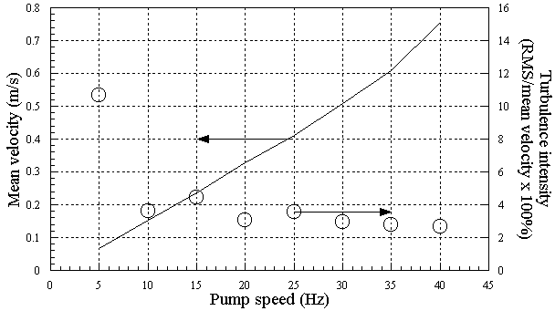
The tunnel is operated by turning on the power using the handle located underneath the contraction on the left hand side. The control panel (located adjacent to the test section) will light up. Pushing the 'PANEL/REMOTE' key (located to left) and then the 'RUN' key actually starts the pump, which accelerates top slow speed. The up and down arrows can then be used to adjust the pump frequency and thus the flow speed given approximately by Figure 8 . Watch the pump setting as you change it - it's easy to overshoot.
Provided with the water tunnel are a digital camera, a steel rulers, caliper and tape measure with which you can check dimensions and positions. This is a good time to open the log book and start taking pictures of apparatus.
B. Cylinder model
A circular cylinder 0.750 inches in diameter is mounted close to the
mid height of the test section. The cylinder is manufactured from brass and
spans the entire test section width (that means, of course, that the ends of the
cylinder are in the boundary layers on the side walls of the water tunnel test
section.
C. Instrumentation for Measuring the Properties of Water
The properties of water are remarkably constant with pressure (an increase
in the atmospheric pressure by a factor of 100 would only have a 0.5% effect
on density). They are however a function of temperature. A small digital
thermometer mounted next to the water tunnel test section monitors the
water temperature. To read the temperature, insert the end of the thermocouple
cable attached to the thermometer through the hole in the top of the test
section. You will need to wait about 5 minutes for the reading to stabilize.
Do not leave the cable immersed in the water for a long period (e.g. at
the end of your test) as it may corrode. Tables for the density and kinematic
viscosity of water can be found in numerous textbooks (e.g. Shames, 1992).
The following calculator uses a quintic fit to these tables. The uncertainties
in the curve fits are ±4x10⁻⁹
m2s-1 and ±0.04kg m-3
D. Laser Doppler Anemometer System
You will have at your disposal a DANTEC Flowlite LDA system to measure
flow velocities. This a dual beam single component system. It consists
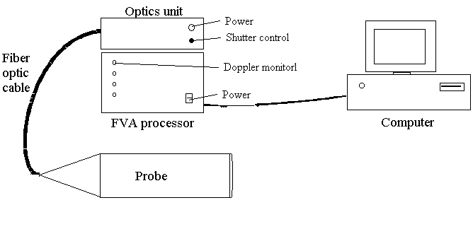
of a probe, fiber-optic cable, an optics unit and FVA enhanced signal processor
( Figure 10). An interface card installed
the computer allows the FVA to be controlled and read from the computer.
This system uses a 10mW Helium Neon laser which produces light of wavelength
632.8nm. The laser and beam splitter are housed in the optics unit. A Bragg
cell, used to shift the frequency of one of the beams by 40MHz is also
installed here. Light from the two beams is passed through two optical
fibers to the probe, where the beams are positioned and then focused using
a lens. The lens also changes the direction of the beams causing them to
cross at the point where they are focused and produce a tiny measurement
volume, some 400mm from the sending lens. The probe operates in backscatter
mode. In fact, light scattered by particles passing through the measurement
volume is collected by the same lens used to focus the beams. It is then
focused into a third optical fiber which carries this light back to the
optics unit where it is fed into a photomultiplier (PM) tube. The following
are the nominal optical characteristics of the system,
| 1. Focal length | 400mm |
| 2. Beam separation at sending lens | 38mm |
| 3. Gaussian beam diameter at sending lens1 | 1.3mm |
| 4. Measurement volume diameter | 0.248mm |
| 5. Fringe spacing | 6.667 |
| 6. Number of fringes in measurement volume | 37 |
Signals from the PM tube are sent to the FVA processor. This is an autocorrelation processor that is interfaced to one of the lab computer. The burst detection criteria and processing parameters of the processor are set from the computer, which is also used to read the results. The FVA processor also has four BNC output ports. The top one, labeled DOPPLER MONITOR outputs the high-pass filtered PM tube signal. The high-pass filter removes the pedestal. A Kenwood CS 2110 100Mhz oscilloscope is connected to this signal to monitor the bursts, which usually look like Figure 6 except with many more cycles in each burst.
The Flowlite probe is mounted on a 3-axis traverse gear made from a milling machine base. Being so heavy the traverse gear provides a stable means of positioning the measurement volume at any point in the test section. The probe mount also allows the probe to be rotated about its axis by 90 degrees, to change the component of the velocity being measured (which remember is parallel to the plane of the beams). This is done by loosening the Allen-head bolt on the collar holding the LDA probe. The scribe marks indicate a rotation of 90 degrees. The probe can thus be used to measure either horizontal or vertical velocity component.
DANTEC FVA Flow Software, version 1.41, is used to control the LDA system from the lab computer, and to collect the measurements made.
E. Seeding of the water flow
The tap water used to fill the tunnel should naturally contain the seeding
particles needed to perform LDA measurements. However, these particles have a
tendency to settle out over time, and you may find that you are not getting
enough samples to make a satisfactory measurement. You should be concerned about
this if you are getting less than about 5 samples per second. If this is the case, let your
TA know, and they will arrange for seeding to be added or the facility to be refilled.
_______________
1The light intensity in
a laser beam is not constant but usually varies as a Gaussian with distance
from its center. Laser beam diameters are therefore usually quoted in terms
of standard deviations of the Gaussian. The Gaussian beam diameter is 4
standard deviations and thus contains 95% of the laser light.
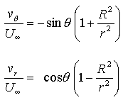 .........................(1)
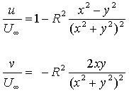 .........................(2)
B. Uncertainties in statistically averaged velocities
A large part of the uncertainty in a quantity determined by a averaging
a set of samples, such as the time mean velocity measured by an LDA, can
be caused by the fact that only a limited number of samples are used to
calculate the average.
Consider a set of N samples of a fluctuating velocity u1, u2, u3 ... uN. The average, or mean velocity, would usually be estimated from the N samples as
 .........................(3)
 .........................(4)
 .........................(5)
 .........................(6)
 .........................(7)
|
Laser light is emitted by the Flowlite probe. Laser light can be harmful
to your eyes.
|
A. Getting familiar with the equipment and ready for an experiment
The following procedures are designed to help you
get a feel for the water tunnel, the cylinder model and the LDA.
Feel free to play with the apparatus at this stage, but don't forget to
record any results, thoughts, ideas or concerns in the logbook. One important
thing to consider when using the fiber optic LDA, is that like all
instrumentation that is pushing the bounds of technology to obtain the most
accurate measurement, this device is temperamental and takes some getting used
to. Setting up an LDA to make a measurement from scratch can take days or weeks,
so don't feel frustrated if, in the space of a 2-hour 45-minute lab, the measurements
don't go too quickly or the data rate is slow. You are obtaining
research-quality measurements - each one you get is a significant achievement.
Goal 1. Design and implement a series of tests to determine the shape and form of the circular cylinder wake at the center span at a fixed Reynolds number.The group should leave few minutes at the end of the lab period for discussion and to check that everybody has everything they need. As a group go through the exit checklist.
Suggestions. Don't forget to record and explain your choice of conditions (i.e. flow speed) and measurement locations in the logbook. If you measured wake structure in experiment 3, at the much higher Reynolds number of the wind tunnel, measuring at some of the same streamwise locations (relative to the cylinder center and its diameter) would also provide a valuable comparison. Its usually easiest to measure the wake in a series of vertical profiles. Don't forget you can measure both vertical and horizontal velocity components. (If you measure both vertical and horizontal mean velocities at the same actual points you can determine the magnitude and direction of the mean velocity vector at each point). Analyze and plot your results as you go. Re-measure any funny looking points. Keep careful documentation of what you do, why you do it, set up characteristics, expected results, unexpected results, analysis, photos and plots in the electronic lab book as you proceed. You might be wise to measure the inflow velocity far upstream of the cylinder - since this is the logical velocity to normalize all your measurements on, you might be unwise to trust the nominal calibration (done ages ago, without the cylinder in the flow).
Analysis suggestions for later. Basically you want to present and describe your mean and RMS velocity profiles to, as clearly as possible, reveal the shape and form of the flow, and compare that with the flow vis. Mean velocity profiles show the time average shape of the flow. RMS velocity profiles show how turbulent the flow is in different regions. The flowvis, of course, shows what the flow looks like at each instant. Linking these views is good discussion. Analysis should include uncertainty estimates for all results.Goal 2. Design and implement a series of tests to examine the flow over the front of the cylinder at center-span a set Reynolds number, and compare with ideal flow theory.
Suggestions. The issue here can be "how good is the ideal flow solution over the front of the cylinder, since the flow here isn't separated". Record and explain your choice of conditions for your measurement (i.e. flow speed) and measurement locations in the logbook. Choose your measurement locations to make the comparison with the theory as straightforward as possible. Don't forget you can measure both horizontal and vertical velocity components. Decide if there is value to analyzing the RMS velocities (might they help explain or illustrate differences with the theory). Checking the inflow velocity far upstream of the cylinder might be a wise thing to do since knowing the free stream velocity is critical to comparing with the theory. Analyze and plot your results as you go. Re-measure any funny looking points. Keep careful documentation of what you do, why you do it, set up characteristics, expected results, unexpected results, analysis, photos and plots in the electronic lab book as you proceed. Analysis should include uncertainty estimates for all results.Goal 3. Design and implement a series of tests to reveal the 3-dimensional form of the flow.
Suggestions. You should be able to move the LDA to any point in the test section, so you don't have to be satisfied with just looking at the center plane and imagining things to be the same all the way along the cylinder. Near the ends of the cylinder the flow is probably completely different (after all here it will be flow around a cylindrical protrusion from a wall, where there must be a boundary layer). The issue is how different? and, more to the point, how far does this difference extend out from the walls? all the way to the center of the flow? How can you tell? You could measure profiles spanwise across the cylinder wake to examine this and, if you did enough of these at the same streamwise location you could see the whole cross section (contour plots?). Alternatively you could measure similar vertical profiles at different spanwise stations and compare regular plots. Whatever 3-dimensionality you see you will be left with the question - Does this come from the geometry of the cylinder wall junction, or does it come from 3-dimensionality in the inflow? You could shed some light on this by measuring across the span upstream of the cylinder. Don't forget that good documentation, including thinking about all the possible flaws and (as far as possible) checking them out, will greatly enhance the extent to which you can satisfy this objective. If you measured spanwise wake structure in experiment 3 comparisons would be very interesting, so you might consider measuring at the same relative locations. Analysis should include uncertainty estimates for all results.Other goal ideas. How about looking at Reynolds number effects? How about determining the water tunnel calibration (freestream velocity vs. pump speed) with the cylinder in? How about looking at the boundary layers on the test section walls upstream of the cylinder, on the bottom and top walls? on the side walls?
Title page
As detailed in appendix
1 .
Introduction
Begin this section by stating logical objectives that fit what your
data has shown you.
Then explain in summary form what was done to achieve the objectives. You could follow this with a background discussion of what LDA is and what sources of error there are and/or a description of the basis of ideal flow theory for the circular cylinder. If you can draw on any material additional to the manual that is good. Finishing with a summary of the layout of the rest of the report would work well.
Apparatus and Instrumentation
This section is probably easiest to write in two parts (though that
is not required), one dealing with the water tunnel and the other with
the LDA. In describing the water tunnel give all details relevant to the
experiment (e.g. closed circuit, contraction ratio (if you measured it),
dimensions and shape of test section, flow quality in the empty section
at test conditions, flow speed range and control etc.) You might include
here some of your measurements (e.g. of the inflow velocity) if they are
relevant to describing the characteristics of the facility, as opposed
to the cylinder flow. Also describe the model, its dimensions, its method
of mounting, its vertical position when mounted, the traverse its accuracy
etc. In describing the LDA, explain what type of system was used, its optical
characteristics, the components of the system, the method of traversing,
the location of the measurement volume in the test section, software etc..
To describe all of this, diagrams and/or labeled photographs are very necessary. Take what you like from the manual, but be sure to reference it. You will have to show at least one figure showing the water tunnel test section, model, and model mount in relation to the LDA probe and traverse. Make sure your figure(s) are dimensioned properly. Include your uncertainties in primary measurements in this section
Results and Discussion
A good way to begin is to briefly state what measurements were made
and at what locations and conditions. You should also include here definitions
of the statistical quantities plotted (e.g. mean velocity, RMS velocity
fluctuation), and explanations of how their uncertainties were calculated
and what those uncertainties were. You should reference a table (copied out of
your Excel file) or appendix containing the uncertainty calculation. Early on in the results and discussion
(or even in the apparatus and Instrumentation) you need to define
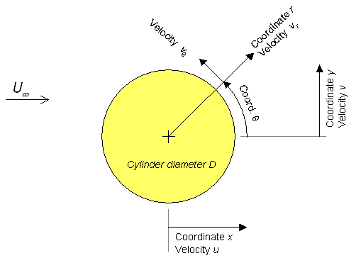
a coordinate system, and any key normalizing variables, using a diagram
and description in the text, e.g. "The coordinate system to be used in
presenting results is shown in figure ??. Coordinate x is measured
downstream from the cylinder center, y vertically upwards from that
center and z, directed so as to complete a right-handed system is
measured from the center span location. Velocity components u and
v
are defined in the directions x and y. Distances will in
general be normalized on the ??? and velocities on the approach
velocity measured at x=??, y=??, z=?? )".
If you have them, now would be a good time to introduce any flowvis pictures. Don't just describe what the static pictures show, use the pictures as a springboard to describing what you actually saw.
Next introduce your profile plots - the kind of wording suggested in experiment 3 will work just fine here. Now describe in detail the plots and error estimates. Then discuss what their significance is given the goals/ objectives you have chosen (look again at the suggestions given with the goals above). One workable approach is to describe what appears on each of the plots in turn, using a separate paragraph for each, inserting sentences of discussion as you go e.g. "Figure ?? shows the profile of uRMS (normalized on free-stream velocity) plotted against y measured at x=?? and z=??. At the limits of the profile, turbulence levels are low at about ?? and reasonably consistent with values measured in the empty test section of ?? (see AOE 3054 course manual, 2002, experiment 4). Presumably these points lie outside the cylinder wake. The wake edges appear to be marked by the large increases in uRMS at around y=?? and ??. The fact that velocity fluctuations in the wake should be larger than outside is consistent with turbulence being present in...".
Make sure your results and discussion include (and justify) the conclusions you want to make and that those conclusions connect with your objectives (if not, change the discussion or the objectives).
Conclusions
Begin this section with one or two sentences describing what you did.
Then draw your conclusions, each numbered and starting on a separate line.
Each conclusion should summarize an important piece of information that
was revealed or taught by the experiment. Make sure the conclusions cover
all the points addressed by your objectives and all the important points
of your discussion. Note that no new material should appear in the conclusions.
It should be possible to write them by simply lifting key sentences from
the rest of your report (mostly the Results and Discussion). Also note
that the conclusions should stand by themselves, though you may refer to
the figures if you wish.
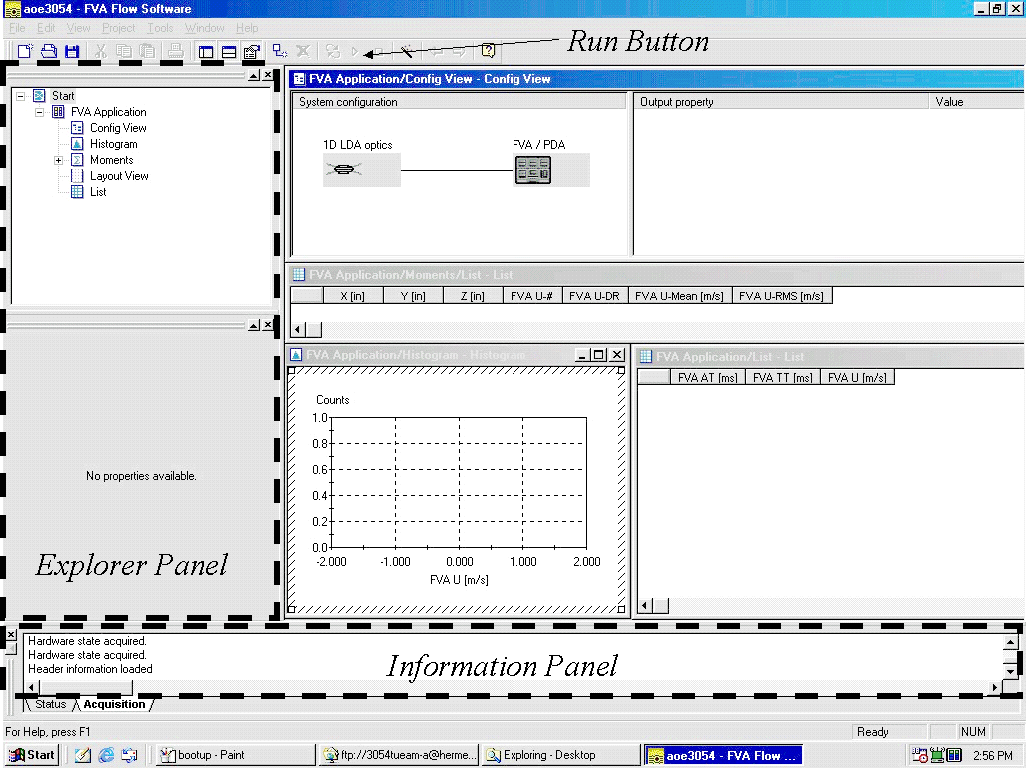
Before starting the acquisition program, turn on the LDA processor and laser system (the two large black boxes). Then double click on the 'FVA flow' icon on the desktop. A program banner appears followed by a dialog box with 3 buttons. Click 'Open Project', select 'aoe3054' and then press 'Open'. The program interface shoud then appear as shown in figure 12. On the left you will see an 'Explorer Panel'. This is where system parameters are set up (the communication with the LDA processor is 2-way) At the bottom of the screen there is an information panel that displays any warning or status messages (you will probably not need to be concerned with this. The rest of the screen includes 'Config View', 'Histogram', 'Moments/List' and 'Application/List' windows.
The Config View Window - Setting Up
The 'Config View' window is where you set up the measurement system.
The window itself shows a block diagram of the system (a '1D LDA optics'
block connected to an 'FVA/PDA' block). Click the mouse on the '1D LDA optics'
block, and you will see all the optical parameters of the system. These
are listed in two places. First in the lower half of the explorer panel
the various external characteristics of the optical system (focal length,
beam diameter at sending lens, etc.). You can change any of these parameters
(if you disagree with the way they are set now) by clicking on them. However,
there should be no need to do this. Second, on the right hand side of the
'Config View' window the measurement volume characteristics implied by
these values are listed. You should note these parameters in the log book.
Note that the dimensions of the measurement (or 'probe') volume are given
as dx, dy and dz, where dz is measured along the bisector of the beams.
Now click on the FVA/PDA block (representing the signal processor). On the right-hand side of the Config View window you will see all the characteristics of the last measurement listed. Since there was no last measurement these are all zero. You may want to keep track of these, or even record some of them when you make each of your measurements. The valid% item indicates the percentage of bursts encountered by the processor that it was able to successfully process. The 'Valid Data Rate' is the average rate at which valid bursts (samples) were collected, and the 'Validated Samples' is simply the number of good samples in the measurement. Note that these two items will also be displayed (and will be easier to record) in the 'Moments/List' window, when you make a measurement.
With the FVA/PDA icon selected the bottom of the explorer panel shows all the processing system parameters that can be set. There are actual several lists of these (selectable from the drop-down menu at the top of this section of the panel), but you only need be concerned with the 'Data Collection' list. The data collection list has 4 items: 'Burst mode', 'Number of bursts', 'Measurement interval', 'Dead time'. With 'Burst mode' set as 'Burst', the processor records the velocity from each burst as one sample. It collects such samples until it has the specified 'Number of Bursts' or until the total length of time for the measurement exceeds the 'Measurement interval'. With 'Burst mode' set as 'Dead time', the processor breaks the total measurement time into a series of periods, each the 'Dead time' long. It then collects only the first burst that it encounters during each interval. This type of data acquisition can lower the particle averaging bias (see above). You can try it later to see what difference it makes. You can also change the number of bursts and measurement interval as you go according to the level of uncertainty you want in your measurements. For now, leave the system set in 'Burst' mode, with 1000 bursts to be collected over a maximum measurement interval of 30secs.
The Results Windows - Taking a Measurement
The other windows on the screen 'Histogram', 'Moments/List' and 'Application/List'
all display the results of a measurement. Since you have no results at
this point they are all empty. To see how these work, take a data point.
Turn on the water tunnel. Click on the 'FVA Application' icon in the top
left of the explorer panel (nothing much will happen when you do this,
but if you don't the program won't take data). Then press the run button
(the small right pointing triangle at the top center of the program window).
You will get a dialog box with a lot of choices and info. Ignore it and
press the 'Acquire' button. For a minute nothing will appear to happen
(but you'll know that the system is working as the run button will be grayed
out). Then as the program collects data it will draw a histrogram, and
the right hand side of the 'Config View' window will show the measurement
characteristics.
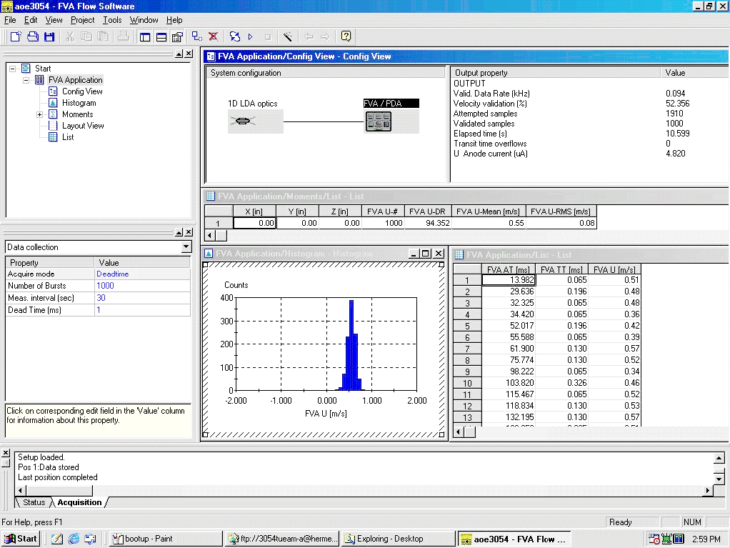
Figure 13 shows how the screen should look after taking your data point. If you didn't get any data, check that both LDA system boxes are turned on, and that nothing is obscuring the laser beams. As a last resort, turn off the computer and both LDA boxes, turn them back on again and try again (this should only very rarely be necessary).
The 'Histogram' window now shows a histogram of the measurement you made. You can scale the histogram or change its features by clicking on this window, and editing the property lists that appear in the bottom half of the explorer panel. Note that changing items in the 'Data' list will only affect subsequent measurements. The other two lists ('Scale' and 'Display') can be used to affect the current results. You can export the histogram to a JPEG figure if you want (to insert into your log book) by right-clicking on the histogram window and making the appropriate selections. You will probably only want to record only representative histograms from a small fraction of your measurements.
The 'Application/List' window shows the time record of the velocity samples measured. The two columns of interest are 'FVA AT' which list the time each sample was measured in milliseconds relative to the time you pressed the Acquire button, and 'FVA U' which lists each velocity sample in meters per second. It may be very valuable to occasionally export these data (again, right click on this pane and make your selections) so your team mates can plot the velocity as a function of time for that measurement. This will be particularly interesting if you have a reasonable data rate >50Hz and are making measurements in the cylinder wake where there may be vortex shedding that will create regular fluctuations in the velocity.
Finally, the 'Moments/List' window displays the velocity statistics. The X, Y and Z columns mean nothing (they will always be zero). You must figure out the location of each measurement for yourself from the traverse gear. The 'FVA U#' column shows the number of valid samples in the measurement, and the 'FVA U-DR' shows the valid data rate. The 'FVA U-mean' shows the average velocity measured, and 'FVA U-RMS' shows the root-mean square velocity fluctuation (i.e. standard deviation). Note that one way of checking for particle average bias over a series of measurements is to plot the data rate against the mean velocity measured. If there is a strong correlation between the two, that may indicate significant bias. While you can export the Moments/List items it is probably easier to select the cells you want, press <CNTRL>C to copy and then paste them into NotePad where you can accumulate a whole sequence of measurements. (You can also add the real X Y and Z to the measurement in NotePad).
You should be ready now to use this system to meet your goals. Don't forget when taking the next or any subsequent measurement to click on the 'FVA Application' icon first, or nothing will happen.
